The Clean Architecture is the term proposed by Uncle Bob, that refers to principles and design practices used for building an architecture for software. It is defined in more abstract way, causing a lot of questions and debates.
This article is intended to explain the most important concepts of The Clean Architecture. Unfortunately Fortunately, this will not be a step-by-step guide. I think that such kind of guides are only applicable in case of technical questions, that don’t require much thinking about a step to be done. All architectural decisions should be well-considered. Some of concepts described in this article may seem absurd at the first glance, however they should make much more sense after you adapt them in your project.
Introduction
The main idea behind the Clean Architecture is quite similar to architectures and concepts described in the previous chapter (Hexagonal, Onion). I would even say all they about the same. Generally, it is just a set of the most strong and important ideas from preceding architectures. Don’t be naive to assume that the Clean Architecture is the silver bullet. Even if you have grasped the ideas, it doesn’t mean that you could apply it everywhere and result in a dramatic codebase improvement and a project success. Using it without solid understanding why do you need it, just because this topic is ubiquitous and everyone tries to apply this architecture, may lead to even worse results than it would be without applying the principles.
How should a good architecture look like?
Before we begin exploring the Clean Architecture, we need to understand why do we need it at all and what features should a good architecture have ? What requirements we expect to be fulfilled by an architecture, and generally what do stakeholders and business expect from a software system?
- Ability to respond as quickly as possible to business changes, making a system competitive.
- A system should be divided into modules separated by boundaries. Any module, detail, delivery mechanism should be swappable, without downtime at best.
- A system should be maintainable, easy to understand, extend and deploy. This will dramatically increase programmers productivity.
- A system should be scalable. An ability to grow horizontally to handle higher loads and big data amounts.
- A software system should have a strong foundation that allows to defer some decisions about implementation details, delivery mechanisms, libraries, etc.
- An architecture should represent and support the intent and use cases of a system.
Inversion of Control. The Dependency Rule

One of the most important and ubiquitous concept that is used almost in every framework is Inversion Of Control. You almost already have heard about this principle, for example working in Java EE world with IoC containers.
One of the most essential ideas in understanding The Clean Architecture is The Dependency Rule. It states that
Source code dependencies can only point inwards. Nothing in an inner circle can know anything at all about something in an outer circle. In particular, the name of something declared in an outer circle must not be mentioned by the code in an inner circle. That includes, functions, classes. variables, or any other named software entity.
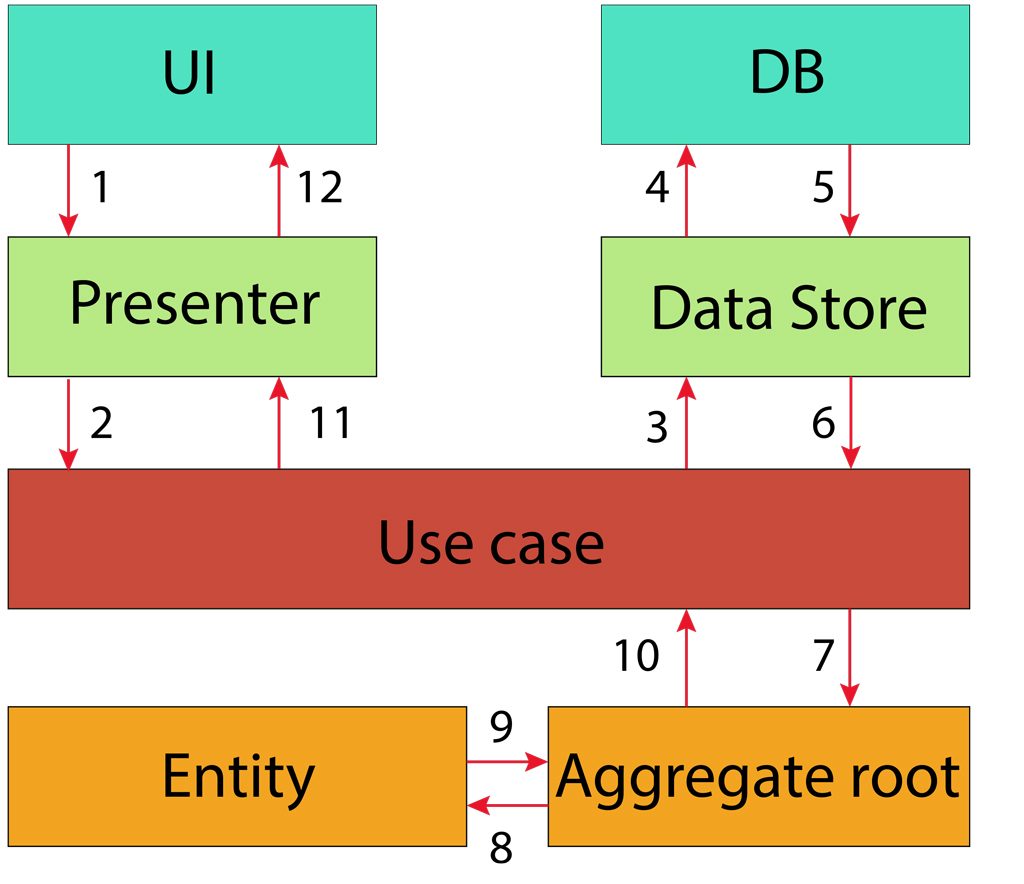
The rule doesn’t directly and tightly related to the concept of Inversion Of Control, however applying the Dependency Rule forces us to apply IoC. And that is good point, let’s find out how is it applied in the Clean Architecture by examining the flow of control. You can find the following diagram in the right bottom corner of the initial architecture diagram.
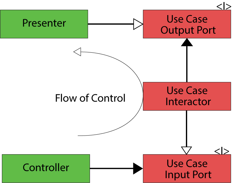
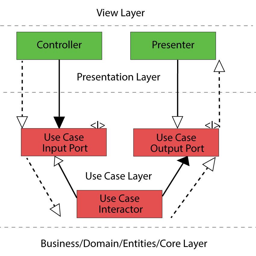
What is it all about? We will transform the diagram a little bit for making more sense and ease of understanding.
Let’s follow this flow step by step. Consider some action like a button click occurred. Don’t pay much attention to different concepts used further, they will be explained in greater details later in the article.
- A button click event is handled in a controller. The controller triggers some method of an object that implements the UseCase Input Port interface.
- We have just crossed the boundary between two layers and are in the UseCase layer now.
- A use case implementation processes the request by orchestrating entities or other domain core objects.
- After getting results from entities the use case implementation invokes a method of an object that implements the UseCase Output interface.
- A Presenter gets result from the Use Case and transforms it to a proper shape followed by passing it to the View layer.
You may also wonder what do these arrows represent? In short, they could be described as follows.
-
 Implements an interface.
  Uses an interface implementation, composition, has-a relation.
One more type of arrows is a dashed one.  These arrows shows a real flow of execution, from the programming point of view it could be represented as a stack of function calls or movement of the Program Counter (PC).
To make a final point in understanding this flow let’s look at the possible code implementing this concept. First of all, let’s define a use case, in this case it will be AddProductToCartUseCase.
1 2 3 4 5 6 7 8 | package ua.com.crosp.solutions.cleanrachitecture.usecase;
public class AddProductToCartUseCase implements AddProductToCartInputPort {
@Override
public void execute(Params params, AddProductToCartOutputPort outputPort) {
// Some entities orchestration
outputPort.onProductAdded();
}
}
|
In the code above we are passing AddProductToCartOutputPort to the execute method, however it could be implemented in other ways, for example the implementation could be injected as a class member. It depends on a concrete project, language, approaches used, etc.
Next we will define AddProductToCartInputPort and AddProductToCartOutputPort interfaces. Please note the package name where all these interfaces are defined.
1 2 3 4 5 6 | package ua.com.crosp.solutions.cleanrachitecture.usecase;
public interface AddProductToCartInputPort {
void execute(Params params, AddProductToCartOutputPort outputPort);
public class Params {
}
}
|
1 2 3 4 | package ua.com.crosp.solutions.cleanrachitecture.usecase;
public interface AddProductToCartOutputPort {
void onProductAdded();
}
|
A Presenter and a Controller might look as follows.
1 2 3 4 5 6 | package ua.com.crosp.solutions.cleanrachitecture.presenter;
public class CartPresenter implements AddProductToCartOutputPort {
@Override
public void onProductAdded() {
}
}
|
1 2 3 4 5 6 7 8 9 10 | package ua.com.crosp.solutions.cleanrachitecture.controller;
public class CartController {
@Inject
protected AddProductToCartInputPort mAddProductToCartInputPort;
@Inject
protected AddProductToCartOutputPort mAddProductToCartOutputPort;
public void onAddProductClick() {
mAddProductToCartInputPort.execute(new AddProductToCartInputPort.Params(), mAddProductToCartOutputPort);
}
}
|
Herein AddProductToCartInputPort and AddProductToCartOutputPort are injected in the Controller class, however it could be implemented differently, as have been already mentioned. However, using both controllers and presenters may seem weird, this is a contentious question, the primary goal here is to understand the flow.
In real projects a Presenter and a Controller are usually combined, but a View should be a separate guy. Please also note that I am not refering to the Controller from the MVC pattern and to the Presenter from the MVP pattern respectively. They just represent a general intent: to control and to present.
1 2 3 4 5 6 7 8 9 10 11 12 13 14 15 | package ua.com.crosp.solutions.cleanrachitecture.controller;
public class CartController implements AddProductToCartOutputPort {
@Inject
protected ProductView mProductView;
@Inject
protected AddProductToCartInputPort mAddProductToCartInputPort;
public void onAddProductClick() {
mAddProductToCartInputPort.execute(new AddProductToCartInputPort.Params(), this);
}
@Override
public void onProductAdded() {
mProductView.updateProduct();
}
}
|
Furthermore, such naming conventions probably should be avoided.
The main idea of the described above is that higher level policies should not depend on details, frameworks, UI, etc. As you may have noted, our AddProductToCartUseCase operates only with interfaces that are defined on the same level as the use case itself. Here comes the power the Dependency Rule represented by inversion of control, dependency injection, dependencies inversion. We can swap an implementation at any time, it should only conform to the defined interface, so our high level rules and policies are isolated from the things that are constantly changing, making the application core stable.
Layers and Circles
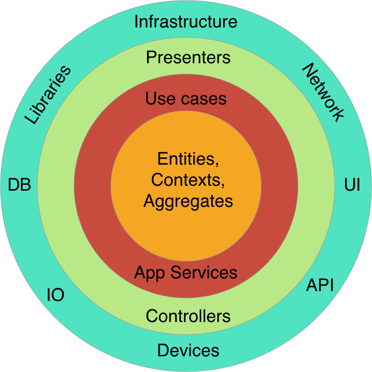
It is the time to understand this diagram. From the first sight it might look weird, because most traditional architectures are defined from top to bottom. Let’s understand this diagram, but before exploring it, it won’t hurt to show the flow of execution on this diagram.
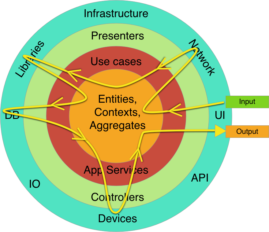
You may wonder what does this curved line represent and why does it pass boundaries back and forth several times. This is just a possible flow when you have a use cases that requires multiple details to perform some action. The term details in this context means any tool (library, db, delivery mechanism, framework, device) that exists on the outermost layer.
For example, when an order is being confirmed, this action requires a lot of steps to be done, like generating invoice, adding history, notifying managers, checking product availability, whatever. Therefore the code execution flow will look something like that curved waved line. Please note that this line doesn’t represent dependencies relationships, dependencies must only point inward like that.
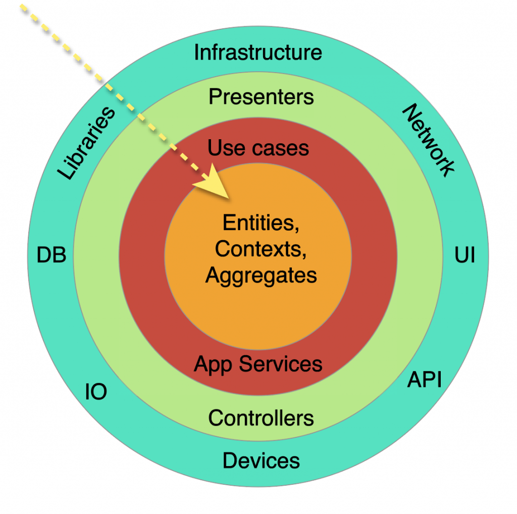
Finally, I will transform the initial diagram to a more common shape for understanding.
This flow is almost present in any application.
- Some external action is occurred, for example a user clicked on a button.
- This event is passed from the View layer to the Presenter layer. A presenter class is tailored for converting data to a proper representation and passing it to a use case class.
- The main duties of the Use Case layer is to control and orchestrate entities and other domain level objects according Application specific rules. But before that domain objects should be created based on data stored in a database or somewhere else. This is usually done through gateways. In this case this the Data Store interface.
- After entities are fetched in the Use Case layer, a Use Case implementation orchestrate entities and domain objects according to Application Specific rules.
- On the diagram I have used the Aggregate root as an entry point to the Domain Core Layer. This term is defined by Domain Driven Design principles.
- When the request is processed according to business rules of an application the result is passed back to the UI layer for example, if required.
I hope these diagrams will help you to understand the Clean Architecture approach better. Now let’s examine each layer separately. We will start from the outermost ring and then will move step by step to the core layer.
Details. Databases. Delivery Mechanisms. UI. Web
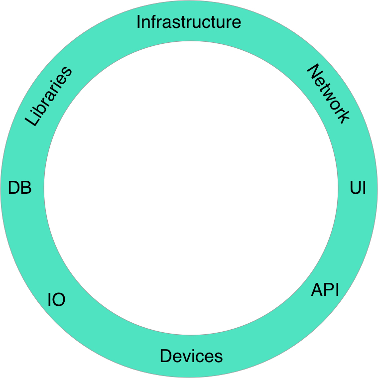
This is the outermost layer on the diagram. It will be probably the largest layer of any system, since there is a variety of devices, libraries and frameworks. They are constantly changing, therefore we should abstract high level (inner layer) policies from details. Let’s go through some of them.
- Network. HTTP, API, Websockets, Sockets. Basically whole the OSI model or any other alternative are just delivery mechanisms.
- UI. Web UI, Native Window UI, Command line, API, ViewControllers, Activities, Fragments. All these examples are just UI mechanisms and therefore details.
- Databases. SQL, NoSQL, in-memory, file-based databases. Databases are just persistence or caching tools.
- Libraries and Frameworks. There are lot of examples could be listed here. We should always try to abstract our core layer in application from libraries, however it is not always possible fully, since some libraries may be crosscutting.
- I/O devices. Input devices (touchscreen, keyboard), persistence devices (NANDs, HDDs), output devices (screen, speaker). Even the Linux Kernel written in C uses the file abstraction for all I/O devices that makes the kernel really powerful and portable.

I guess thats enough examples, the main idea should be clear as far as things on this layer change very frequently we should be protected from this changes by the wall of abstraction and inversion of control. This will not only make a development process much easier, but will also isolate possible bugs. Furthermore, this layer is usually hardly testable because of its changing nature and instability.
Presenters. Controllers. Gateways. Interface Adapters.
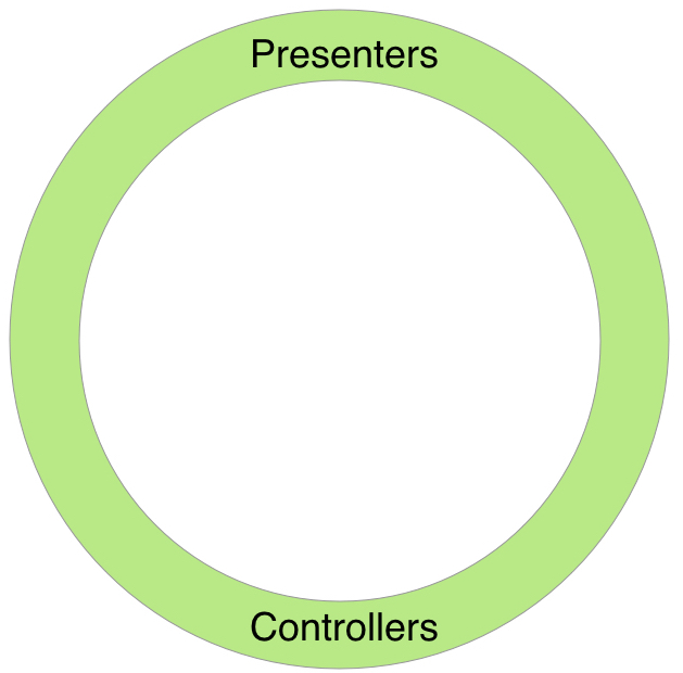
This circle layer is named as Interface Adapters in the original article. That means that all data that is passed to outer or inner layers should be transformed here to a convenient structure for a layer being passed to. For instance, data that is passed to a View primary should contain only String fields, so the view could just display it without any extra work.

You should be already familiar with such design patterns like MVP, MVC, MVVM. I won’t explain each of these design patterns. The concrete one is selected according to project requirements, type of a project and other factors. This layer is just a glue between the outermost details level and the application layer, in that case represented by the UseCase layer. Roughly speaking, the letter M (Model) in the Clean Architecture is embodied by the Use Case layer, but not by Entities or other Core Domain objects. Or the Model could be just the data passed back and forth between the UseCase layer and the Interface Adapters layer.
Views in the Interface Adapters layer
Uncle Bob considers the Views under this layer, however personally I don’t understand what is the reason for that and would put the Views into the outermost layer. If we are talking about a view interface, it could be defined in the Interface Adapters layer.
The next guy that lives on this layer is the Gateway. Generally gateway is just another abstraction that will hide the actual implementation behind, similarly to the Facade Pattern. It could a Data Store (the Repository pattern), an API gateway, etc. Such as Database gateways will have methods to meet the demands of an application. However do not try to hide complex business rules behind such gateways. All queries to the database should relatively simple like CRUD operations, of course some filtering is also acceptable.
This and any further layers should be testable in contrast to the Details layer, that is usually is really hard to test.
Use Cases. Interactors
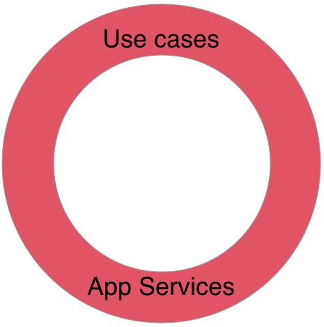
Now things start to get interesting. The Use Case layer is not as trivial for understanding as already discussed layers. And very often there are a lot of misunderstandings about the purpose of this layer.

A Use case is a list of actions and communication steps between a role and an automated system that are required to achieve a goal. This definition contains some important points that are worth detail investigation. A set of use cases is how a user sees a software system from the functionality perspective.
I guess that everyone is aware of the Use Case Diagram. It is used on the first steps of a software system design. The more defined use cases cover possible system operations, the easier it will be to design a proper architecture and choose a development process strategy and methodology.
From the technical point of view, that we are most interested in, a use case mostly is an orchestration of Entities. Entities will be discussed in a while, for now you need to know that they contain Critical Business Rules and dance to the tune of use cases, but according to the business rules. Also there is a term called Interactor. A Use Case and a Interactor are related terms and usually used interchangeably. I think, it would be better to say that an Interactor object implements a Use Case of a system.
The software in this layer contains application specific business rules. It encapsulates and implements all of the use cases of the system.
What does application specific mean in that case ? Application specific rules can be changed if application requirements change. An application in this case is an automated system. For example consider a bank as the core business set of rules. An ATM application will have it’s own rules, a web system for personal account management will have other rules, a mobile application also may have different rules. That’s why these such rules are application specific.
I have found a great use case example in this article. This is a use case of withdrawing money from an ATM.
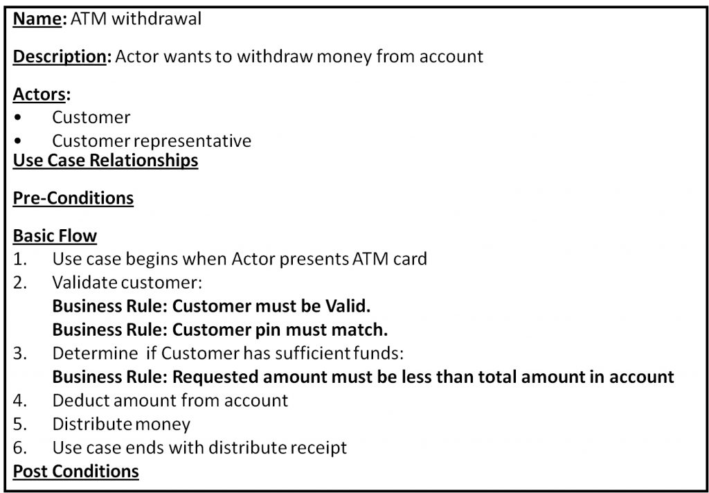
I thinks that is a really good example of separation between Application Specific Rules and Critical Business Rules. Critical Business Rules that belong to the Entities layer are bolded in the use case scenario above. Personally I would put one more step to the business rules, however the idea should be clear.
Usually a use case have some input data required and output result is returned when a use case completes. The result can be represented not only by data directly returned, but a deferred event like a callback function call or just some indication of success. Therefore let’s modify slightly the use case, adding input and output data.
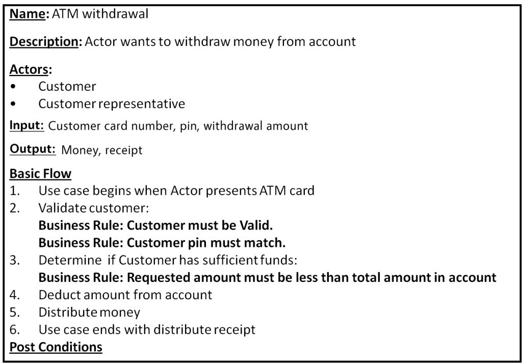
As you can see I have added input and output fields to the use case description. They are specified more from a user’s perspective, not as arguments and the return value for the execute method from an interactor implementation class (for instance).
Usually a use case is a single atomic action. Sometimes developers are mixing multiple related use cases into a single interactor/use case class (as I have done here). This is done to eliminate boilerplate code, however this approach violates Single Responsibility and Separation of Concerns rules. Personally I prefer to keep use cases separately.
Documenting all use cases of a system
Why is it crucial to create use case diagrams for a system being developed ? Have you had a situation when a new developers comes into a project and asks experienced project members about some business rules and use cases of a project ? Even experienced members of a team may have some hesitations before making some changes or bug fixing, caused by non trivial use cases and policies.
Considering all these problems, I suggest to document all possible use cases of a system that users expect from it to perform. Firstly and most importantly you will have a collection of business rules that your client can understand, discuss and change. Secondly, you have a single data store that contains all (at best) possible system use cases and business rules, as a result new members (both developers and stakeholders) have to spend much less time than it would be if they elicited all these information from other team members. Finally it will be much easier to design future development of a system, without even diving into code.
Use cases could be documented in a form of diagrams, scenarios (as shown above), steps & conditions, any form that is convenient for a project, team and stakeholders.
Entities. Domain.
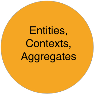
The last and the most important layer from the architecture perspective is the Entities or the Domain Layer. Entities encapsulate Critical Business Rules. Critical Business Rules are rules that support a business existence, but not necessarily a software system presence.

The last and the most important layer from the architecture perspective is the Entities or the Domain Layer. Entities encapsulate Critical Business Rules. Critical Business Rules are rules that support a business existence, but not necessarily a software system presence.
This layer should be the most bulletproof and external changes shouldn’t affect operation of this layer. Entities usually embodies business rules that even make sense even without any software system or application.
From the technical side an Entity is an object that mostly contains methods and logic, not just data. Entities are not DTOs, DAOs.
Designing the Entities layer is not always a trivial task. In case you are developing an enterprise application you will probably spend a lot of time architecting this layer and errors this layer may have really serious consequences. There is a set of really valuable rules called Domain Driven Design. These concepts aims to ease development of large enterprise applications with complex business rules. In case you are not developing an enterprise application, these concepts still are worth your attention. Therefore I encourage you to study the Domain Driven Design approach.
What about simple applications that are not a part of enterprise ? The Entities Layer should contain most general and high-level rules and policies that should not be affected by the changes in upper layers.
Entities must not persist their own state in a database. There are a lot of ORM libraries and framework that impose direct mapping of Entities to the database, however such approach violates the Dependency Rule. For example when a base Entity class extends some Database model class it is still aware about database and other low level details. Some frameworks apply Inversion of Control to solve this problem, other use bytecode weaving, generally speaking Entities should not be aware about existence of a database.
Entities vs Use Cases
One tantalizing question is the difference between Use Cases and Entities layers. When to use one over another ? Here is some comparison between two layers as I understand them.
- Use cases contain application specific rules, on the other hand Entities contain core business rules.
- Use cases usually don’t make much sense without an application, but Entities are the rules and policies that may exists without any automated system.
- Entities contain rules that rarely change and not affected by changes in the outer layers.
- Use cases orchestrate the flow and operation of Entities. All data that is required by Entities or the Domain Layer usually passed through/by the Use Cases or Gateways.
- When application requirements change, at best there should not be any modifications made in the Domain Layer (Entities), but most of changes will happen in the Use Case and Details layers. However, when some core business rules are modified then these changes will be mapped on the Entities layer.
Conclusion
In this article I’ve tried to share my experience of understanding and applying the Clean Architecture principles. All described rules and concepts may be really valuable if used correctly. Otherwise they may cause much more mud and spaghetti in your project. Therefore novice developers should get enough experience before applying these rules.
These rules should not be strictly followed, I would say that the Clean Architecture is just a set of practices that should give an idea about further decisions and design steps regarding a software shape. Every project requires a unique approach that should be made by an architect based on a lot of factors.
If you have any questions regarding the article, please feel free to contact me or post comments below, discussion is always a great way to reach a consensus.
Hi, my name is Molochko Alexander, I am Interested in different areas of software development, curious about learning and discussing architectural and software patterns, examining internals and understanding how everything works under the hood.
Recent posts
- Mar 1, 2020 Implementing Laravel custom Auth Guard and Provider
- Feb 16, 2019 Hacking Java Applications with Byte Buddy and Decompilers
- Jan 5, 2019 Page Specific Dynamic Angular Components using Child Routes
- Oct 13, 2018 Understanding Dagger 2 Scopes Under The Hood
- Jul 21, 2018 Understanding and using Xdebug with PHPStorm and Magento remotely
Popular posts
- 135108 Views How to Install The Latest Apache Server (httpd) on Centos 7
- 98172 Views Routing network traffic through a transparent SOCKS5 proxy using DD-WRT
- 69713 Views Android Reverse Engineering: Debugging Smali in Smalidea
- 69021 Views How to Unbrick TP-Link WiFi Router WR841ND using TFTP and Wireshark
- 55518 Views Clean Architecture : Part 2 – The Clean Architecture